Advanced Tool Paths Improve Cutter Performance in Difficult Materials
*by Mike MacArthur, as published in MoldMaking Technology, October 2009
The Common Ground Between Moldmaking and Aerospace article in the March 2009 issue (page 31) discussed some advanced programming techniques, such as trochoidal toolpaths. This article will cover the topic in much greater detail.
Definition and Benefits
Trochoidal (tro-koid’l) toolpaths are curves connected with a circle that roll along a straight line or path.
Heat
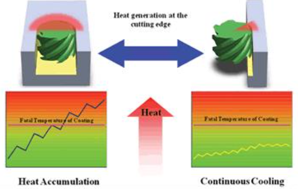
By using trochoidal paths you can minimize heat build-up. Controlling heat is paramount in getting consistent performance from high quality tools in difficult alloys. Heat dramatically reduces tool life and is a major cause of tool failure. The reason trochoidal toolpaths reduce heat is the curved paths minimize the arc of engagement. By using a smaller cutter and arcing the tool in the cut, the amount of contact with material is minimized and the flute spends less time in the cut.
Speed
There are also other advantages to using trochoidal toolpaths. Because heat is minimized you can cut materials at much faster SFM. And with trochoidal paths you can take deeper depth-of-cuts in the Z-direction. Typically the Z depth-of-cut can be up to two times the diameter of the cutter. Trochoidal toolpaths are mostly used to create slots. You can use trochoidal paths to create pockets, but there will be some wasted movement when the pocket opens up, and the arcing paths are unnecessary to minimize engagement. Typically, you use a tool 50 to 62 percent of the slot width. By staying in this range you can minimize the arc of engagement enough to take advantage of the increased rpm and Z depth-of-cut. The amount of radial step-over (X,Y direction) will depend on the material, but ranges between 2 to 10 percent of the cutter diameter. These lighter radial cuts allow much faster rpm and feedrates, making the process very productive without increasing heat (Figure 1).
Tool Selection
Smaller diameter tools are typically used, reducing the cost of the cutter and lowering the overall expense of manufacture. You want to make sure the tools you select for this type of cutting are specifically designed not only for trochoidal cutting, but also for the material you are cutting. Proper coatings, material substrate and geometries are essential to high-performance machining.
Software
There are CAD/CAM systems today that have taken the trochoidal toolpaths even further. Instead of just using the typical trochoidal path, they actually control the arc of engagement. Essentially the amount of engagement does not increase even when you enter a corner or other complex geometry.
The tool sounds the same in corners as it does in straight line cuts. This helps eliminate variations in finish and accuracy. The tool has constant tool pressures that do not fluctuate as the part geometry varies.
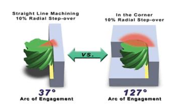
In general, if you are using a tool with a 10-percent radial step-over in straight line machining (profiling), the arc of engagement is 37 degrees, but when you hit a corner the angle increases to 127 degrees (Figure 2). This spike in engagement increases heat and tool pressure, causing problems with tool life and part quality.
Some CAD/CAM systems incorporate hybrid paths using trochoidal-type movement in corners and tight areas, while in more open sections use traditional toolpaths. What does this mean to the programmer? More predictable tool life and consistent parts.
It is easy to program a part using these new hybrid toolpaths. All you have to do is enter the typical information and the radial step-over you want. The CAD/CAM system will handle the rest and control the angle of engagement.
Test Cases
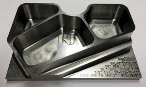
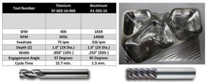
This programming was put to practical use on a couple of sample parts. The first part is a 6Al4V titanium block 6″ x 4″ x 1-1/2″ machined with a 1/2″ diameter 6-flute cutter. The feedrate was 75 ipm. and 400 sfm. The radial width-of-cut was .050″ (10%) and 1″ axial depth (2X). The entire part was machined from solid in 15 minutes (Figure 3). See the video at moldmakingtechnology.com/articles/100902.html.
The same programming approach was used in aluminum as well using a 1/2″ diameter 3-flute tool with aluminum chatter reduction geometry. This part was cut at 14,000 rpm and 336 ipm. The entire 6″ x 4″ x 1-1/2″ part was machined in 1 min. 30 sec. There was no squeal or variation in sound when the tool cut the corners because the tool’s contact remained the same even in the corner (Figure 3).
In another application a slot was cut in a hardened rasp/file using a 3/8″-diameter, 6-flute cutter designed for hardened tool steel. The tool cut the part at 125 ipm. See the video at moldmakingtechnology.com/articles/100902.html.
Summary
By using newer programming techniques, difficult material can be cut easily. Use smaller diameter tools to minimize the arc of engagement and control heat. Many newer materials entering the market tend to be more exotic and difficult to cut. Use specific cutter geometry for each application. By using trochoidal toolpaths and hybrid trochoidal toolpaths you can successfully machine these exotic materials.