Choosing the Right Cutting Tool for the Mold Making Industry
Choosing the right tool will pay huge dividends in the quality, repeatability and the overall success of a job. This article discusses the different types of materials, which tools to choose, and how to use them.
Applications
There are three major applications in the machining of molds.
- Pre-hardened Materials (30-65 HRc)
- Annealed or softer materials (less than 30 HRc)
- Graphite electrodes for EDM.
Each of these mold materials has specific cutting tool geometries, carbide grades, coatings, and techniques that ensure the best material removal rates and the longest tool life.
Pre-Hard Material 30-65 HRc:
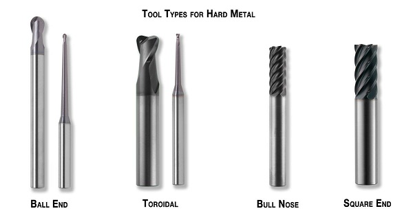
Starting with the harder materials that run up to 65 HRc. the four common (and recommended) tool types for cutting pre-hardened mold materials are 1) Ball End, 2) Toroidal, 3) Multi-fluted Bull Nose cutters, and 4) Square End tools.
For 3-D cuts the number one “go to” choice is the ball end cutter. The ball end cutter with advanced coatings is the primary choice for three-dimensional cutting of cavities and cores.
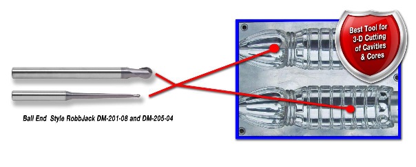
The best way to apply ball nose cutters is to rough out the part in a constant Z-level roughing routine. This is a cutting path that roughs the part out at a constant Z-Depth and uses an X or Y step-over to produce the three-dimensional shape. Climb milling is the preferred cutting direction. Using this type of tool path helps reduce the amount of heat produced and will result in cuts that are closer to the finished shape required. If you have to use a raster tool path, make sure not to zig-zag the tool and cut in a climb mill direction only. During roughing or semi-finishing operations, typical radial step-overs (X or Y axis movements) are 25-40% of the diameter of the cutter. Axial depth of cuts (Z-depth) depends on the hardness of the part. For 30-40 HRc, use a Z-depth of 10% of the cutter diameter per pass. For 40-50 HRc material, use a Z-depth of 5% of the cutter diameter per pass and for materials greater than 50 HRc use a Z-depth of 4% of the cutter diameter.
The toroidal type of tools is best for tight areas like helical bores and ribs, or when the cutter diameter is close to the radius of the part. The toroidal shape gives many advantages over other cutters. These cutters are able to cut flat floors with larger step-overs than ball nose cutters but are much better suited for tight areas. By sticking with a 2-flute cutter and the toroidal shape surface contact, heat, and deflection issues are minimized.
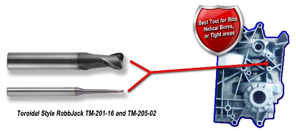
When using Toroidal tools on the side of the cutter for profiling applications the hardness of the material affects the radial step-over. For materials 30-50 HRc, use a step-over of 5% of the tool diameter per pass. If the material is harder than 50 HRc, use a step-over of 2%. In both cases, a Z-depth of 1 x the diameter of the cutter per pass can be used. If you using the tool like a face mill (cutting on the end of the tool only) on flat floors or doing helical bores, the radial step over is 25% of the cutter diameter and 2% in Z-depth per pass. If going down in a helix use a 2-3 degree helix angle.
Bull nose cutters work best for wide-open areas with flat floors or straight walls. This tool works best to profile the outside shape with straight walls or very wide-open areas because of number of flutes.
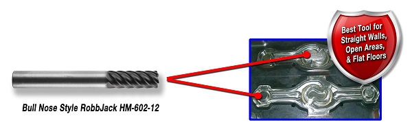
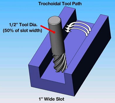
The high number of flutes allows for faster feed rates but the programmer must minimize the amount of contact with the cutter and use light radial width cuts. Smaller diameter tools reduce the amount of surface contact so operations with less rigid machines benefit using smaller diameter tools. Multi-fluted Bull Nose cutters are applied the same way as toroidal tools. Use the same step-overs and depth of cuts as the above diagrams. Multi-fluted bull nose tools can cut slots in hardened materials when using trochoidal tool paths or new tool paths that control the angle of engagement of the cutter. It is important to make sure the tool is about 50% of the slot width to allow for enough movement and ensure the angle of engagement does not increase and generate too much heat.
The very last tool you want to use for pre-hardened materials is the square end cutter. All the force and heat are focused on the corner of the tool. If heavy amounts of material are removed with a sharp corner the tool will tend to chip. For this reason square end tools should only be used to pick out the small radius left from a toroidal or bull nose cutter when sharp corners are required.
Annealed or softer materials:
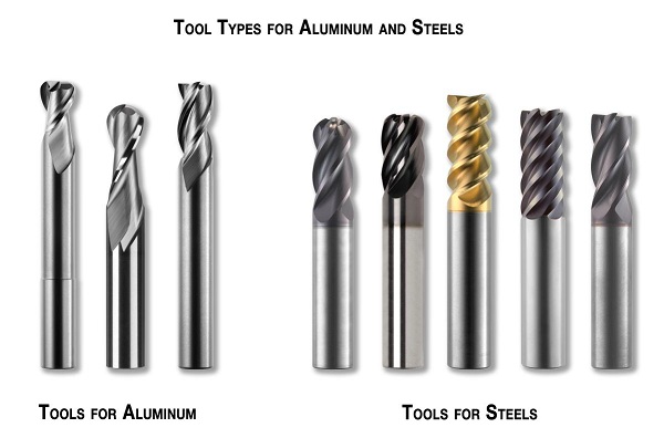
These materials range from steel mold bases to aluminum materials. There are many types of tools used for this category of mold materials.
Less care needs to be taken in programming techniques with softer material, but many of the same techniques used for difficult-to-machine and harder materials are used for softer material. Many companies are choosing to use tool paths that control the engagement angle of the cutter and reduce heat build-up.
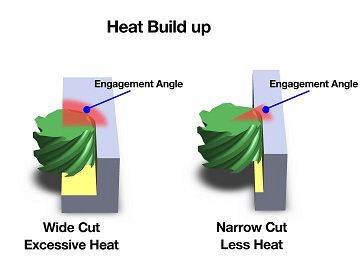
In addition, CAD/CAM systems exist today that have taken the trochoidal tool paths even further. Instead of just using the typical trochoidal path, they actually control the engagement angle. Essentially the amount of engagement does not increase even when entering a corner or other complex geometry. The tool sounds the same in corners as it does in straight line cuts. This helps eliminate variations in finish and accuracy. The tool has constant tool pressures that do not fluctuate as the part geometry varies and helps to control excessive heat. In general, if using a tool with a 10% radial step-over in straight-line machining (profiling), the arc of engagement is 37 degrees. But when a corner is hit, the angle increases to 127 degrees.
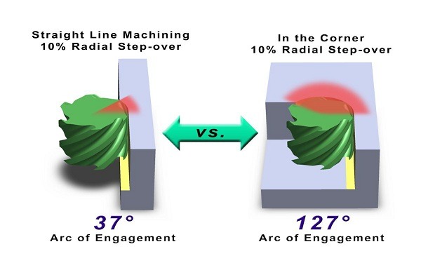
This spike in engagement increases heat and tool pressure, causing problems with tool life and part quality. Some CAD/CAM systems incorporate the new hybrid paths and control the angle of engagement keeping it constant in corners and tight areas, while in more open sections use more traditional tool paths. What does this mean to the programmer? It means more predictable tool life and consistent parts. It is easy to program a part using these new hybrid tool paths. The programmer simply has to enter the typical information and the radial step-over desired. The CAD/CAM system will handle the rest and control the angle of engagement.
Graphite Machining:
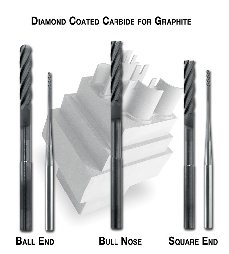
The three major types for graphite machining are ball end, bull nose, and square end. Diamond-coated carbide tools are used to extend the tool life when cutting EDM electrodes. When cutting graphite, abrasive wear is where the difficulty lies. Cutter path and technique are not as critical, so usually the electrode shape dictates the type of cutter used. Diamond-coated tools are widely used for this type of cutting due to the added wear resistances of the true diamond coating. Tool life ranges between 10-30 times longer than uncoated carbide cutters. Some graphite shapes require very sharp cutting edges for thin ribs, sharp geometry, or small parts.
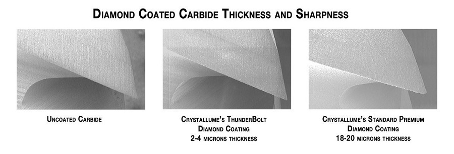
Previous generations of diamond coatings could not be used in these applications and carbide was the only option, but now there are thinner diamond coatings available with the advantages of sharp carbide tools but with the added wear resistance of a true diamond coating. Having this thinner diamond available not only helps in those difficult applications, but also helps reduce the cost of the diamond-coated carbide tools. Because of the availability of various diamond coating thicknesses, mold makers that do not have high production quantities or need less expensive tools now have choices. They can use tools that are less expensive than thick diamond but still have the advantages of very long lasting true diamond coated carbide tools. The new diamond coatings are available in thicknesses from 2 microns to 20 microns as standard. Crystallume’s Thunderbolt ™ coating is about 2-4 microns and is great for finishing of electrodes for ribs or other critical areas.
For more information from RobbJack Corporation call (916) 645-6045, e-mail mike@robbjack.com, or visit robbjack.com.
Contributor
Mike MacArthur is the National Sales Manager for RobbJack Corporation, Lincoln, CA and is responsible for research, development and technical assistance. He is actively involved in developing tools and processes for hard metal machining and aerospace applications.ead