Don't Fear High Speed Hard Metal
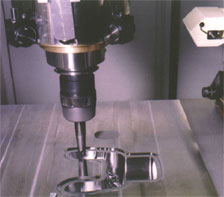
High Speed Machining (HSM) of hardened die steels should not be feared but embraced.
Many people feel that hard metal machining is a black art, but with a few basic principles it is not only profitable but also a straightforward machining process. There are several components of the process which include: the effective utilization of the machine tool, cutting tools, tool holders, and programming. If these areas are addressed correctly, hard metal machining looses its mystery and mystique and becomes a predictable process where established formulae and guidelines can be used. In this article, the focus is on the cutting tool but other areas will be addressed as well.

Choosing the Process
There are three major machining methods: soft machining, hard machining, and EDM. The configuration and hardness of the die or mold material determine which method or combination of methods will work best. Soft machining–machining the part prior to heat treatment–should be considered when machining large or parts that require deep cuts. Semi-finishing and finishing can then be done in the hardened state. If the part is not very large or calls for shallow machining, the entire part can be milled in the hardened state. If the part geometry requires thin features and deep cuts, EDM may be the only option.
Tool Selection
Choosing the proper cutting tool is very important when machining hardened metal. There are three basic designs of cutters: ball end, corner radius (bullnose) or square end (Figure 1). The first choice in hard metal machining should be the ball end mill. The ball end mill should be used for roughing operations and most finishing operations. Its large radius dissipates the force and heat that is generated in cutting hard material at high speeds and feeds. The ball end mill allows the user to cut closer to the net three-dimensional shape and allows for higher speeds and feeds.
If a part requires large, flat areas on its floor, a corner radius tool should be used after the ball end tool has roughed out the part. The corner radius tool does not have as large of a radius as the ball and therefore does not dissipate the heat and force as well as the ball end mill. The square corner tool should be used as a last resort and only after a ball end and corner radius tool has removed as much material as possible from the part. The sharp corner, of a square end tool, acts as a focal point for all the heat and force and will have a tendency to chip. The only time a square end mill should be used is when a sharp corner is required at the transition of a floor and a wall.
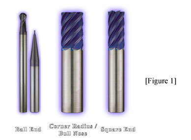 Tool rigidity is also an important factor to consider. In small diameter cutters the shank of the tool should be much larger than the cutting diameter (Figure 1). This increases the stiffness of the cutter, which helps produce better finishes and affords longer tool life.
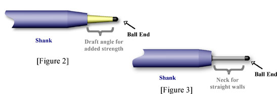
It is important to choose the tool to fit the application as closely as possible. For example, RobbJack’s DM and MDM series end mills come with an 8 degree per side draft angle. Yet at the factory it is very easy to modify this angle and can be done very quickly. If the part has 3° draft, the tool can be modified to 21⁄2° draft. Generally, a tool should have 1⁄2° less draft than the actual part. This 1⁄2° provides for angular clearance while keeping the tool as strong as possible (Figure 2). Additionally, the tool should not project from the holder any farther than is required. If straight walls are required, a neck can be utilized to strengthen the tool (Figure 3). Both methods allow the short-length-of-cut tool to cut deeper than its cutting length.
Controlling Heat Generation
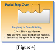
Excessive heat changes the part’s surface morphology, which reduces cutting accuracy. However, one way of minimizing heat generation and retention is by controlling the radial step-over of the cutting tool. Radial step-over is the distance between centerlines of successive, parallel cuts (Figure 4). For roughing operations, the radial step-over should equal 25 to 40 percent of the cutter’s diameter. For finishing with a given cusp height on a flat surface, the radial step-over can be calculated with the following formula:
![]()
where cusp height is the chordal deviation–finish tolerance. Similarly, cusp height can be found using the following:
![]()
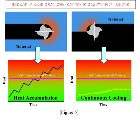
Radial-step-over determines how much heat is accumulated in the tool and the part by determining the length of time each flute spends in the cut and the amount of time it cools before entering the cut again (Figure 5). The graphical representation illustrates the effects of radial-step-over and heat generation. When the step-over is too great, the flute builds up heat because there is insufficient time to cool the flute before it reenters the part. By using smaller step-overs, there is a continuous cooling action which controls heat generation. By regulating the heat generation with a continuous cooling action, higher rpms can be used without reaching the fatal temperature of the coating (Figure 5). Once the fatal temperature of the coating is reached, there is a rapid deterioration of the cutting edge which increases force and temperature to the tool and part. When the proper process is implemented there should be no build up of heat in the part. Excessive heat leads to changes in the surface morphology and loss of cutting accuracy.
By selecting the proper coating, higher temperatures can be reached without compromising the cutting tool. For example, the maximum working temperature for Titanium Carbonitride (TiCN) is 750° F (400° C) compared to Titanium Aluminum Nitride (TiAlN) with a maximum working temperature of 1470° F (800° C). Generally, TiAlN is the preferred coating for HSM of hardened die/mold materials because of its high heat resistance. The higher heat resistance of the TiAlN coating enables the use of faster RPMs without damaging the cutting tool.
 Proper speeds and feeds are essential in controlling heat build up. Large chip loads remove heat with the chip so it does not build up in the tool or part. If the chip load is too light there is a rubbing or grinding type action which leads to heat build up. Therefore, it is very important for tool life to use the largest chip load possible without damaging the tool or part (Figure 6).
For example, if the chip load per tooth should be 0.008” and the chip load used is .002”, a part that should take 20 minutes to machine now takes 80 minutes. This means the tool spent four times as much time in the cut as required.
The geometry of the tool also plays an important role in controlling heat. The geometry of the tool affects the way the chip is formed and evacuated from the cut. Incorrect geometry can result in premature tool failure and poor part finishes. This is why a tool should be designed specifically for hard metal machining.
Flood coolant should not be used in most cases. The result of extensive testing by RobbJack shows that using flood coolant in materials above 40 HRC reduces tool life, on average, five fold. We have tested many methods of coolant delivery including: through-the-tool coolant holes, coolant grooves, coolant hoses, high pressure, normal pressure and have found in all cases, there was a reduction in tool life. The reason for the reduction in tool life is thermal shocking of the carbide tool. It is however, very important to evacuate the chips and avoid re-cutting. Two excellent methods of evacuating chips are air or mist coolant. The air or mist should be directed as close to the tip of the tool as possible.
Tool Issues
When to replace a tool depends on the user’s requirements. Generally, cutter failure can be seen with the naked eye. A simple way to check is to look at the tip of the tool while the tool is in the cut. When the cutter is worn the increased  force and heat is evident in a red glow at the tip of the cutter. Turning off the light on the machine tool aids in seeing the glow (Figure 7). The red glow begins slowly and usually appears in corners or areas where more material is being removed. When there is a prominent, continuous red glow the tool is usually pulled and replaced. The red glow can also indicate problem areas in the part where there is improper programming.
Consistent tooling is also important to making the process predicable. It is very important to consider the tolerances of the tools. To get proper fit in tool holders, including shrink-fit tool holders, the tolerance on the tool shank should be -0.0001” to – 0.0002” of the nominal diameter. This ensures compatibility, consistency, and better surface contact with tool holders. Industry standard tolerances are up to -0.0005”. This leads to runout in the holder and improper fit. In addition, the roundness of the shank should be held to at least ±0.000025″.
Runout causes the chip load to increase for one or more flute, while the other flutes cut too light of a chip–a major problem in hard-metal machining. Shock from runout causes the tool or workpiece to vibrate, leading to chatter and tool chipping. Controlling runout limits the shock introduced to the cutter.
Polished shanks should also be avoided. While the tools may appear aesthetically pleasing, polished shanks reduce the holder’s gripping ability. Having the proper tolerances on the tool and tool holder will insure proper rigidity, accuracy, and consistency.
The Machine Tool
The machine tool should not be overlooked. Although it is possible to machine hard metal parts on older machines it is not as productive. If the machine is limited on RPM the feed rate will proportionally suffer. It is beneficial to have a machine with the closest accuracy and with the most rigidity possible. To maximize feed rates, the controller must be able to compensate for acceleration, deceleration, and spindle growth. The controller also plays an important role in the ability to process the vast amount of information required for die/mold machining at high speeds. When looking for a new machine tool it is not only important to investigate the look ahead of the controller but also its throughput capabilities. The throughput capabilities consist of the block processing speed, the servo response, the interpolation rate, the resolution of the feedback system, and acceleration and mass.
Programming
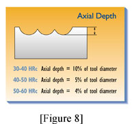
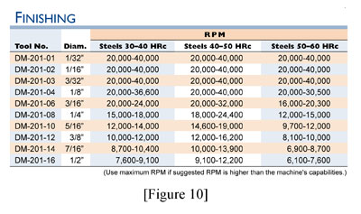
Programming determines the way the tool engages the material as well as the type of forces induced into the tool. Therefore, programming is a critical element to the success of a HSM of hardened metal . When entering a cavity, helical interpolation should be used to minimize the variations of shock induced into the cutter. Programs should avoid Straight plunging (plunging in the Z-axis only). If the programmer cannot set the tool to enter the part from the side or helically, he should program it to ramp in. The programmer, who also determines the radial step-over and depth of cut, is critical to the HSM process. There are established parameters that can be used to insure success in HSM of hardened material (Figure 4, Figure 6, Figure 8, Figure 9, and Figure 10)

The Process
It is important to remember that HSM of die and mold steels is a process that consists of the effective utilization of the machine tools, the cutting tools, the tool holders, and programming. All the components need to be addressed to ensure that predictable and profitable performance will result.
For more information from RobbJack Corporation call (916) 645-6045, e-mail mike@robbjack.com, or visit robbjack.com.